Product family

Flow, Pressure & Temperature Sensors

Flow, pressure and temperature sensors selected by measurement requirements, fluid connections and electrical interfaces.

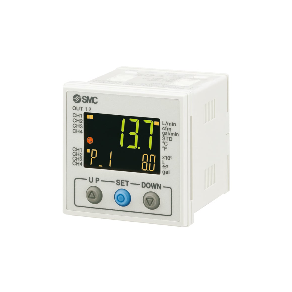
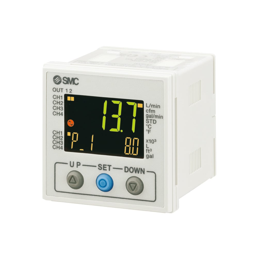
SMC PFG200 four-channel flow monitor, standalone manufacturer catalogue photograph.
Representative component · configuration-specific

Component selection

All Product drafts

5 results
Private preview · candidate records

5 local draft records. Includes unfinished records and Family overviews. Draft · Noindex. Reference configurations are not approved stock. Image public-use review remains separate.

Show content-ready drafts
SMC PFG200 four-channel flow monitor, standalone manufacturer catalogue photograph.

LCP-000104

Four-Channel Flow Monitor — SMC PFG200 Reference

A separate three-screen monitor for up to four compatible flow-sensor channels. The original product photo shows the display unit alone; fluid-contacting sensors…

Accumulated flow
Monitor can manage accumulated flow for up to four lines
Product type
Separate three-screen, four-channel flow monitor; sensing heads are separate products
View specifications
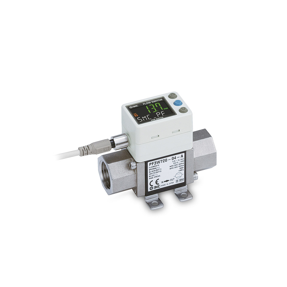
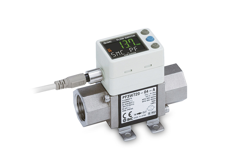
SMC PF3W720-04-A integrated-display water flow sensor, official product photograph; front label identifies the pictured configuration.

LCP-000064

Integrated Water Flow Sensor — SMC PF3W720-04-A Reference

An official 800 × 532 product photograph clearly identifies PF3W720-04-A, with a built-in display and two threaded fluid ports. The corresponding maker's…

Configuration and ports
PF3W720 integrated-display flow sensor; 04 = Rc 1/2 ports; A = NPN/NPN switching outputs
Rated flow range
2–16 L/min nominal rated flow range
View specifications

Specify with confidence

The details that shape your selection.

Measured variable: flow, pressure or temperature Required range, accuracy and response conditions Electrical output/interface and power supply Coolant, wetted material and process connection Mounting, calibration/documentation requirements and quantity

  • Function and loop position
  • Interfaces, drawing revisions and envelope
  • Coolant, materials and seals
  • Temperature, pressure and flow conditions
  • Testing and documentation
  • Quantities and delivery requirements

Overview

Flow, pressure and temperature sensors address different measurement points and electrical interfaces. A suitable measuring principle must be evaluated for the fluid, range and installation position.

Configuration and selection

Define the variable, expected range, accuracy basis, response need, process connection and wetted materials. Include output, power, calibration and integration requirements.

Information to prepare

  • Measured variable: flow, pressure or temperature
  • Required range, accuracy and response conditions
  • Electrical output/interface and power supply
  • Coolant, wetted material and process connection
  • Mounting, calibration/documentation requirements and quantity

Configuration and quotation

Include the drawing or specification revision and identify any requirements that are still to be confirmed. Available configurations, testing and documentation are confirmed with quotation.

Documented reference configurations & supporting imagery

Local editorial preview

Documented configurations and product references

Manufacturer examples retain their model and conditions. These references describe source products, not approved stock or supply. Images are pending final selection and rights review.

ifm — family reference

ParameterDocumented value / configuration
Measured variableflow; temperature; pressure

ifm — SU family

ParameterDocumented value / configuration
RangeInline SU family is presented with flow measurement up to 6,000 L/min; exact model range required.
OutputIO-Link digital signal is offered in the SU family.
Process connectionexternal clamp-on; threaded; tri-clamp; flange
Wetted materialInline version uses a stainless-steel measuring tube; clamp-on version is external.

ifm — SU family comparison

ParameterDocumented value / configuration
Accuracy basisclamp on: ±5%; inline glycol or oil: ±5%; inline water: ±2%; repeatability: ±0.2%Conditions: basis: manufacturer family comparison; exact model and installation conditions required

ifm electronic — SU6031

ParameterDocumented value / configuration
Powercurrent consumption: below 75 mA; operating voltage: 18 to 32 V DC SELV/PELV; power on delay s: 5
ResponseIO Link min cycle ms: 9.6; flow T09 s: below 0.25 with dAP=0; temperature T05 s: 5.7; temperature T09 s: 86
Range0.5 to 65 L/min; -20 to 100 degrees C
Accuracy basis35 percent glycol: ±(5.0% measured value + 0.5% full-scale end value); repeatability: ±0.2% full-scale end value; water: ±(2.0% measured value + 0.5% full-scale end value)
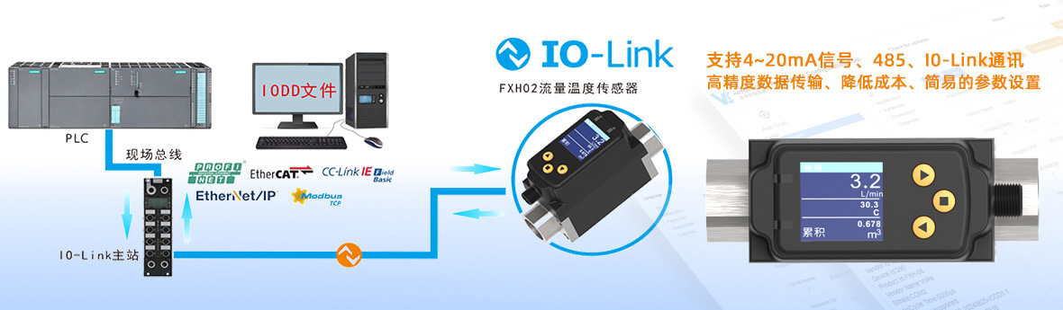
Outputswitching; pulse; 4-20 mA analogue; IO-Link; frequency; diagnostic; totalizer
Process connectionG 1/2 external thread, DN15
Wetted material316L stainless steel pipe section; NBR reinforced-fibre flat seal

Danfoss — DST P1XX installation guide / 000803

ParameterDocumented value / configuration
Electrical connector variantsM12 4-pin / 5-pin, Metri-Pack 150, AMP seal 16, Deutsch DT04 3-pin / 4-pin, ISO 15170 bayonet and DIN connector examplesConditions: Guide covers multiple variants, not a complete individual ordering code; scope: DST P1XX installation-family examples; not all options belong to every DST P140 ordering code
Process connection configurationThe SAE female-flare variant is illustrated without a gasket; it uses the mating flare sealing surface.Conditions: Guide covers multiple variants, not a complete individual ordering code; scope: SAE female flare only; do not apply to threaded G or NPT configurations or the generic DST P140 image

KATU — FTS400

ParameterDocumented value / configuration
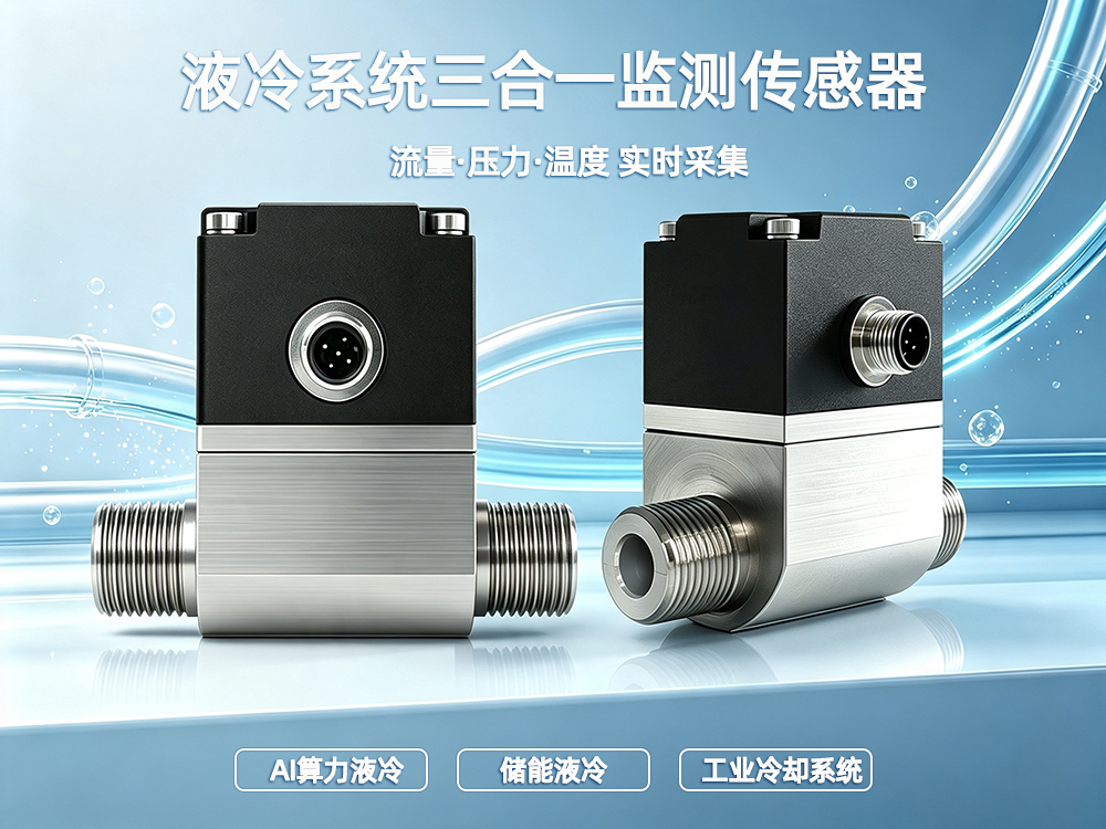
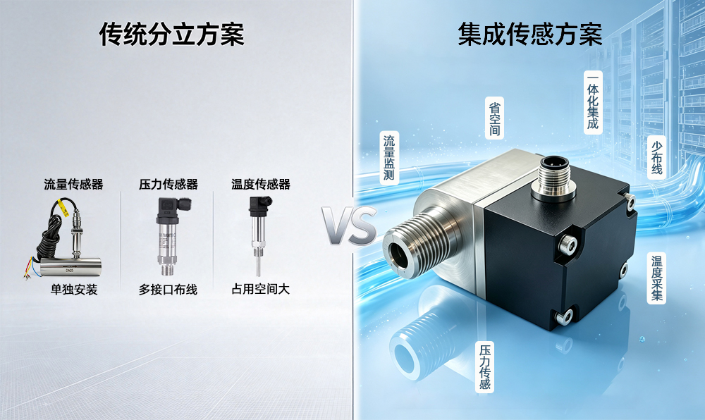
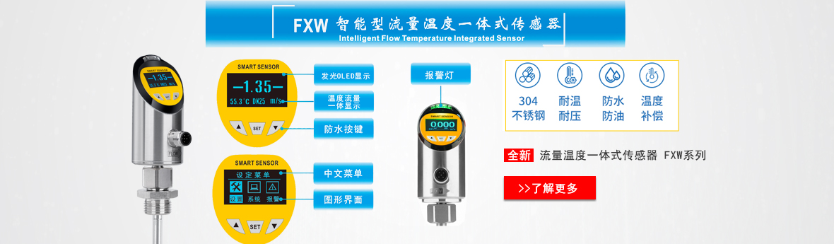
Measured variablesFlow, pressure and temperatureConditions: Attributed manufacturer series/configuration example only; not site stock or capability; scope: Reference series, not all options simultaneously. Exact size/calibration/coolant and order code need the matching datasheet. Optional high-temperature/high-pressure marketing ranges are not imported.
Pressure measurement range0 to 1.0 MPaConditions: Attributed manufacturer series/configuration example only; not site stock or capability; scope: Reference series, not all options simultaneously. Exact size/calibration/coolant and order code need the matching datasheet. Optional high-temperature/high-pressure marketing ranges are not imported.
Standard medium temperature-20 to +80 degCConditions: Attributed manufacturer series/configuration example only; not site stock or capability; scope: Reference series, not all options simultaneously. Exact size/calibration/coolant and order code need the matching datasheet. Optional high-temperature/high-pressure marketing ranges are not imported.
Ambient temperature-10 to +65 degCConditions: Attributed manufacturer series/configuration example only; not site stock or capability; scope: Reference series, not all options simultaneously. Exact size/calibration/coolant and order code need the matching datasheet. Optional high-temperature/high-pressure marketing ranges are not imported.
Wetted materialsAlumina / SUS304 stainless steelConditions: Attributed manufacturer series/configuration example only; not site stock or capability; scope: Reference series, not all options simultaneously. Exact size/calibration/coolant and order code need the matching datasheet. Optional high-temperature/high-pressure marketing ranges are not imported.
Power supply18 to 30 VDCConditions: Attributed manufacturer series/configuration example only; not site stock or capability; scope: Reference series, not all options simultaneously. Exact size/calibration/coolant and order code need the matching datasheet. Optional high-temperature/high-pressure marketing ranges are not imported.
Analog outputThree-wire 4-20 mA; maximum load 500 ohmConditions: Attributed manufacturer series/configuration example only; not site stock or capability; scope: Reference series, not all options simultaneously. Exact size/calibration/coolant and order code need the matching datasheet. Optional high-temperature/high-pressure marketing ranges are not imported.
Digital outputRS485 stated in product overview; protocol/order configuration must matchConditions: Attributed manufacturer series/configuration example only; not site stock or capability; scope: Reference series, not all options simultaneously. Exact size/calibration/coolant and order code need the matching datasheet. Optional high-temperature/high-pressure marketing ranges are not imported.
Process connectionsG1/2 to G2 threaded options; DN15 to DN250 flanged options listedConditions: Attributed manufacturer series/configuration example only; not site stock or capability; scope: Reference series, not all options simultaneously. Exact size/calibration/coolant and order code need the matching datasheet. Optional high-temperature/high-pressure marketing ranges are not imported.
Display1.44 TFT colour displayConditions: Attributed manufacturer series/configuration example only; not site stock or capability; scope: Reference series, not all options simultaneously. Exact size/calibration/coolant and order code need the matching datasheet. Optional high-temperature/high-pressure marketing ranges are not imported.
Accuracy basisFlow: page states < +/-2% FS; pressure: < +/-0.5% FS; temperature: < +/-1 degCConditions: Attributed manufacturer series/configuration example only; not site stock or capability; scope: Reference series, not all options simultaneously. Exact size/calibration/coolant and order code need the matching datasheet. Optional high-temperature/high-pressure marketing ranges are not imported.
Flow span selectionSelect flow span from the pipe-size table; the broad page range is not one instrument spanConditions: Attributed manufacturer series/configuration example only; not site stock or capability; scope: Reference series, not all options simultaneously. Exact size/calibration/coolant and order code need the matching datasheet. Optional high-temperature/high-pressure marketing ranges are not imported.

VOLKE — FJP

ParameterDocumented value / configuration
Measured variablesFlow, pressure and temperatureConditions: scope: single integrated housing; exact output version to be selected
Flow measurement principleHall-sensed impellerConditions: scope: supplier product description; fluid properties and calibration affect measurement
Nominal diameter optionsDN6, DN8, DN10, DN15, DN20, DN25Conditions: scope: series size options, not one universal body or flow range
Dn6 listed flow range0.5 to 10 L/minConditions: scope: DN6 row; stated flow accuracy grade 3–5 is not a guarantee for all fluids
Dn15 listed flow range5 to 50 L/minConditions: scope: DN15 row; measurement accuracy conditions require controlled manual
Dn25 listed flow range12 to 120 L/minConditions: scope: DN25 row; do not apply to smaller fittings
Listed thread optionsG1/2 for DN6–DN15; G3/4 for DN20; G1 for DN25Conditions: scope: manufacturer table; verify each order-code and mating seal
Listed temperature measurement range0 to 100 degCConditions: scope: measurement span, not a combined process-temperature or coolant compatibility rating
Listed supply voltage24 VDCConditions: scope: supplier webpage summary; wiring variant must be confirmed
Listed process interface material304 stainless steelConditions: scope: interface only, not a complete wetted-material statement
Listed output choicesThree 4–20 mA channels or RS485Conditions: scope: supplier webpage lists options; verify exact version, protocol and pinout before specifying

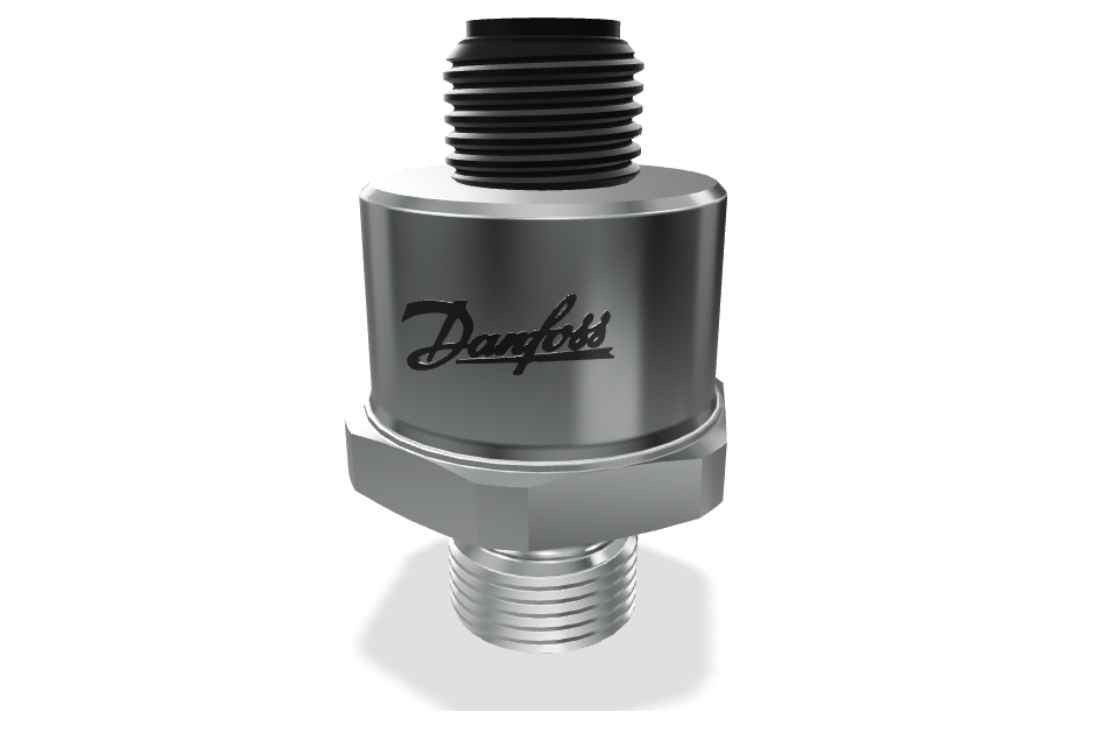
Danfoss — Danfoss DST P140 pressure transmitter series

ParameterDocumented value / configuration
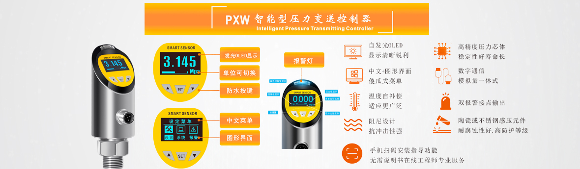
Documented applicationLiquid-cooling data-center pressure monitoringConditions: scope: Series application statement; exact order-code specification not established
Sensing and body designMEMS sensing technology with stainless-steel design and hermetically sealed media interfaceConditions: scope: Series description; wetted alloy and pressure range require order code
Diagnostic optionAutomatic sensor-failure detection described as an optional diagnostic capabilityConditions: scope: Optional, not claimed on all DST P140 variants

SMC — SMC PF3W720-04-A

ParameterDocumented value / configuration
Configuration and portsPF3W720 integrated-display flow sensor; 04 = Rc 1/2 ports; A = NPN/NPN switching outputsConditions: scope: Official photograph label reads PF3W720-04-A; PDF defines suffix
Rated flow range2–16 L/min nominal rated flow rangeConditions: scope: For PF3W720 column; not the display or settable range
Medium and fluid temperatureWater or ethylene-glycol aqueous solution at viscosity below 3 mPa·s; fluid temperature 0–90 °C without freezing/condensationConditions: scope: Glycol measurement range depends on concentration/viscosity; check chart and calibration
Working and proof pressure0–1 MPa operating pressure; 1.5 MPa proof pressureConditions: scope: Proof is not continuous working pressure
Switching outputA output code = two NPN switching outputsConditions: scope: Confirm I/O wiring and cable suffix for purchase
Power and enclosure12–24 VDC ±10%; IP65 enclosureConditions: scope: See exact ordered electrical configuration
Listed wetted materialsPPS, SUS304, FKM and SCS13 listed for fluid-contact portions of PF3W seriesConditions: scope: Catalogue list for PF3W; confirm exact complete wetted bill of materials

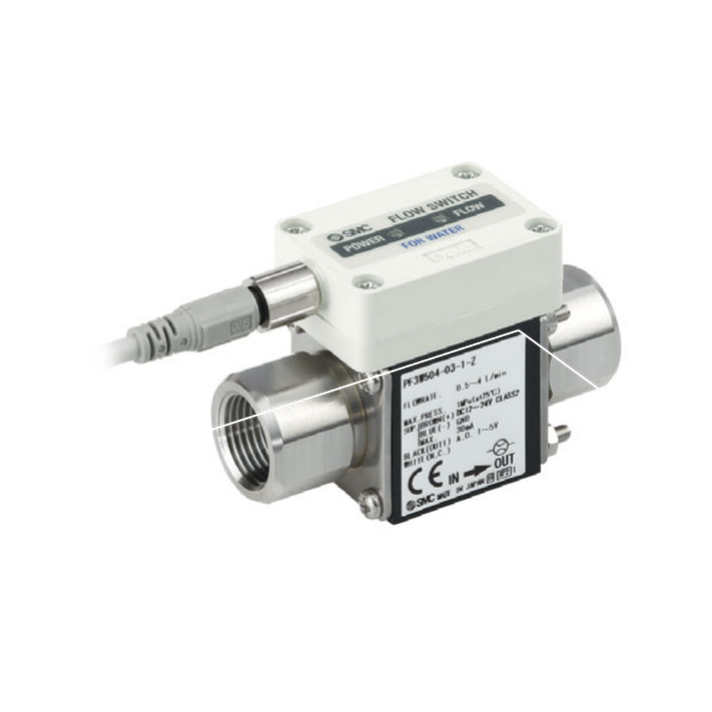
SMC — PF3W504-03-1-Z

ParameterDocumented value / configuration
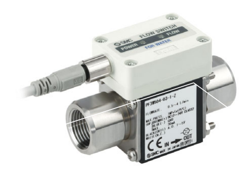
Product typeRemote sensor unit for water flow monitoring; separate display/monitor is a different component
Rated flow range0.5–4 L/min marked on the pictured unit; not a range for all PF3W5 models
Analog output1–5 V marked on the pictured unit
Supply voltageDC 12–24 V marked on the pictured unit
Process port size and thread boundaryPF3W504 size code 03 uses 3/8 in piping ports; catalog dimensions separately identify Rc/NPT and G thread-form variantsConditions: scope: The 3/8 in port size is supported for PF3W504; verify the complete suffix/thread form before specifying a mating fitting

SMC — PFG200 Series

ParameterDocumented value / configuration
Product typeSeparate three-screen, four-channel flow monitor; sensing heads are separate products
Channel capacityUp to four compatible flow sensors can be connected
Sensor compatibilityListed compatible SMC sensor families: PF2A, PF3W-Z, PF3W and PF2D; verify input/output code
Accumulated flowMonitor can manage accumulated flow for up to four lines
Analog input boundaryHub function supports a 1–5 V analogue-voltage sensor output; actual monitor configuration must be selected

Danfoss — Danfoss DST P140 075G4027

ParameterDocumented value / configuration
Gauge pressure range0 to 10 barConditions: scope: Old manufacturer datasheet copy; current Danfoss Design Center also lists 0–10 bar gauge for this code. Measuring span, not overpressure or site supply rating
Output signal4 to 20 mAConditions: scope: Current Danfoss Design Center also lists 4–20 mA for this exact code
Process and electrical connectionsG 1/4 A male pressure connection to ISO 1179-2; M12 × 1 electrical connectionConditions: scope: Current Danfoss Design Center independently lists the same code's G 1/4-A and M12 × 1 interfaces; mating connector is a separate installation input
Supply voltage8 to 28 VDCConditions: scope: Series data sheet specification for the 4–20 mA option; current exact-code Danfoss Design Center lists 8–28 V DC

Danfoss — Danfoss DST P140 series

ParameterDocumented value / configuration
Wetted materialsAISI 304L and AISI 316L listed for wetted partsConditions: scope: Current Danfoss Design Center shows 304L/316L for 075G4027; coolant and seal compatibility still require application review

Configuration options and selection inputs

Calibration

Magnetic flowmeters require conductive media; conductivity threshold and accuracy differ by family.

Reference: ifm — family reference

Calibration

Accuracy basis changes by fluid and additive concentration; exact model/media curve and installation lengths (5xDN inlet, 1xDN outlet) must be preserved.

Reference: ifm electronic — SU6031

Pin assignment gate

Determine pin assignments from the exact product code engineering sheet; connector appearance alone is insufficient.

Reference: Danfoss — DST P1XX installation guide / 000803

Conditions: Guide covers multiple variants, not a complete individual ordering code; scope: No generic pinout or supply-voltage range assigned to the existing reference image

Ingress protection conditions

Protection depends on correctly fitted mating connectors. The guide does not permit high-pressure water or steam cleaning merely because IP67 is stated.

Reference: Danfoss — DST P1XX installation guide / 000803

Conditions: Guide covers multiple variants, not a complete individual ordering code; scope: Select and verify connector/assembly rating for the ordered configuration