Technical selection
Specifications and configuration
Reference — FJP
| Parameter | Documented value / configuration |
|---|---|
| Measured variables | Flow, pressure and temperatureConditions: scope: single integrated housing; exact output version to be selected |
| Flow measurement principle | Hall-sensed impellerConditions: scope: supplier product description; fluid properties and calibration affect measurement |
| Nominal diameter options | DN6, DN8, DN10, DN15, DN20, DN25Conditions: scope: series size options, not one universal body or flow range |
| Dn6 listed flow range | 0.5 to 10 L/minConditions: scope: DN6 row; stated flow accuracy grade 3–5 is not a guarantee for all fluids |
| Dn15 listed flow range | 5 to 50 L/minConditions: scope: DN15 row; measurement accuracy conditions require controlled manual |
| Dn25 listed flow range | 12 to 120 L/minConditions: scope: DN25 row; do not apply to smaller fittings |
| Listed thread options | G1/2 for DN6–DN15; G3/4 for DN20; G1 for DN25Conditions: scope: manufacturer table; verify each order-code and mating seal |
| Listed temperature measurement range | 0 to 100 degCConditions: scope: measurement span, not a combined process-temperature or coolant compatibility rating |
| Listed supply voltage | 24 VDCConditions: scope: supplier webpage summary; wiring variant must be confirmed |
| Listed process interface material | 304 stainless steelConditions: scope: interface only, not a complete wetted-material statement |
| Listed output choices | Three 4–20 mA channels or RS485Conditions: scope: supplier webpage lists options; verify exact version, protocol and pinout before specifying |
Manufacturer series reference. Confirm the exact order code, mating parts and stated conditions for the quoted configuration.
Overview
The FJP series places flow, pressure and temperature sensing in an in-line component for a liquid-cooling branch. The page covers a documented series with several bore sizes, not one universal order code with a single flow span.
Construction and interfaces
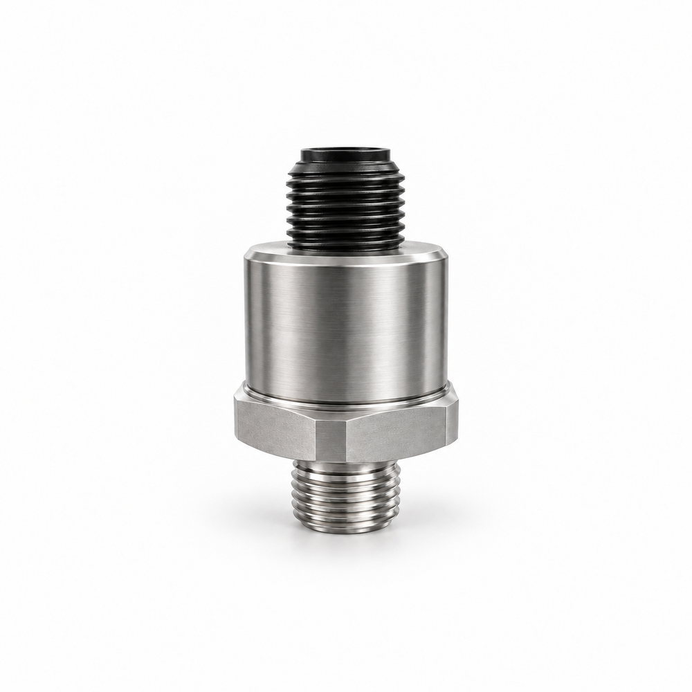
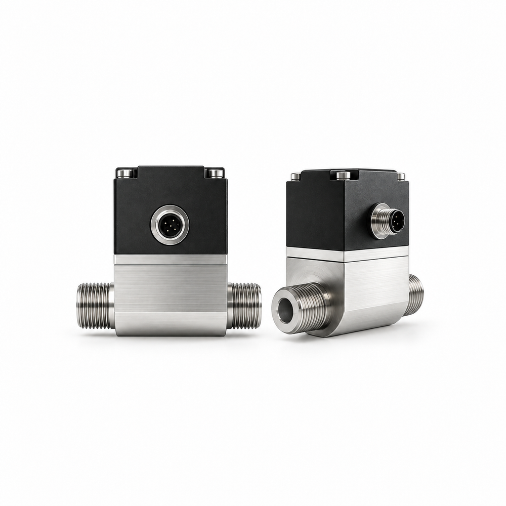
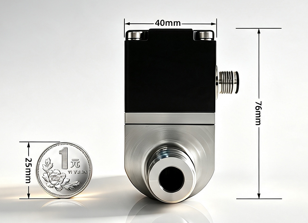
The manufacturer describes an impeller with Hall-sensed rotation for flow, combined with separate pressure and temperature sensing elements. The reference picture shows a formed body, two fluid ports and an electrical connection; exact dimensions follow the selected variant.
Selection
Choose the nominal size using the size-specific manufacturer flow table and check the corresponding thread. DN6, DN15 and DN25 rows have different flow spans; their endpoints cannot be pooled into a rating for one instrument.
Configuration options
The supplier lists RS485 and three-channel analog outputs as alternatives to clarify by order code. State the communication protocol, cable or connector, required voltage, calibration fluid and display or controller integration when requesting a configuration.
Application limits
The listed temperature value is a measurement range, not evidence that every FJP configuration is compatible with every coolant at that process temperature. The pressure range printed on the source page is malformed and is deliberately excluded pending a controlled manual.