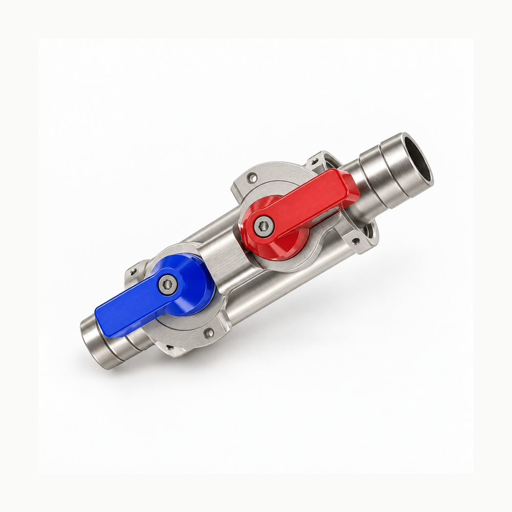
Technical selection
Specifications and configuration
Reference — FND interlocking valve pair
| Parameter | Documented value / configuration |
|---|---|
| Construction | Two matching ball-valve bodies are connected by a bidirectional interlock for supply/return operation |
| Body material | SUS304 stainless steel body; EPDM listed as standard sealing-ring material |
| Listed media | PG25 and DI water listed for the FND series, subject to ordered configuration and operating conditions |
| Listed nominal bore options | FND25 and FND40 nominal-bore variants are tabulated separately; the maker labels them 25 (1 in) and 40 (2 in)Conditions: scope: Manufacturer series labels; nominal codes are not measured internal diameters or interchangeable end fittings |
| Series max working pressure | 150 psi maximum working pressure in the FND series table psiConditions: scope: Maker series statement; verify selected valve-half, seal, end connection and complete pair for actual duty |
| Listed operating temperature range | -15 to 80 degCConditions: scope: FND series range; coolant and selected seal compatibility remain separate |
Manufacturer series reference. Confirm the exact order code, mating parts and stated conditions for the quoted configuration.
Overview
The FND arrangement links two ball-valve bodies with an interlock for selected supply and return line operation. It is a mechanical connection component, not a generic pair of unrelated valves.
Construction and interfaces
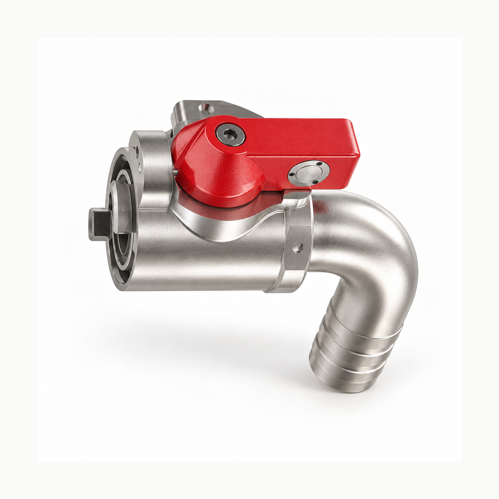
The manufacturer's red/blue product rendering shows both valve halves in the linked configuration. The source lists SUS304 bodies and EPDM sealing rings for the FND series; exact terminations are order choices.
Selection
Choose a matched supply/return configuration with the correct mating connector, hose or threaded ends. The manufacturer lists PG25 and DI water for the series, but the actual coolant and duty still need code-specific review.
Configuration options
FND25 and FND40 families include straight, elbow-barb, threaded and clamp terminations; these are alternate ordered interfaces, not all present on the pictured pair.
Application limits
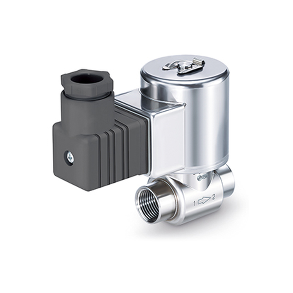
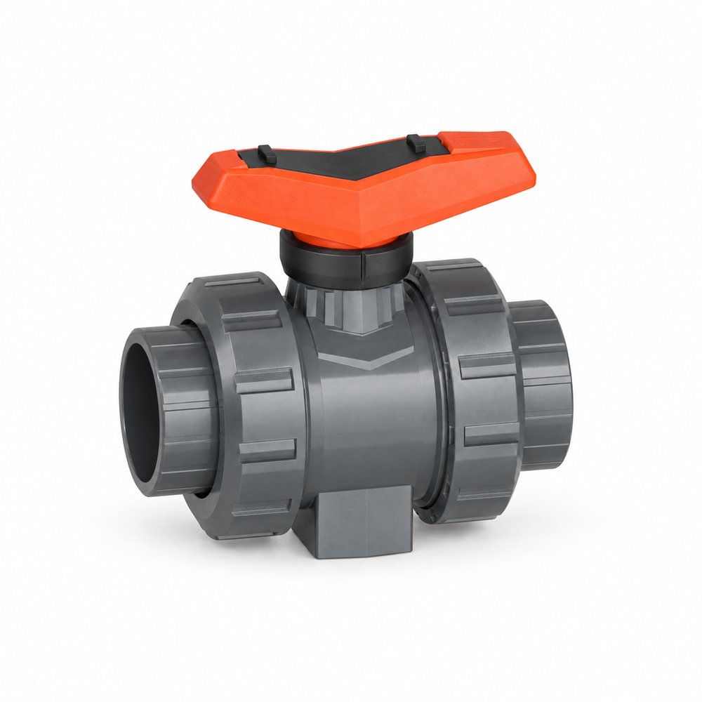
Do not interpret a generic FND photograph as a pressure or leakage guarantee for an arbitrary selected end configuration. Confirm interlock sequence and the complete mating assembly before procurement.