Technical selection
Specifications and configuration
Reference — CYSBI
| Parameter | Documented value / configuration |
|---|---|
| Effective diameter options | DN3 to DN12Conditions: scope: series range; select exact order code |
| Body material | Aluminum alloyConditions: scope: body statement; wetted material and coating need exact drawing |
| Maximum misalignment compensation | ±0.5 mmConditions: scope: manufacturer series claim; installed mounting must be verified |
| Retention | No integral locking; requires external structure for lockingConditions: scope: series description |
| Listed working pressure | 20 bar listed for the CYSBI series barConditions: scope: Manufacturer series summary; confirm exact fixed-mount pair and operating conditions |
| Listed operating temperature | -40 to +125 degCConditions: scope: Manufacturer series summary; not a universal seal or coolant compatibility claim |
Manufacturer series reference. Confirm the exact order code, mating parts and stated conditions for the quoted configuration.
Overview
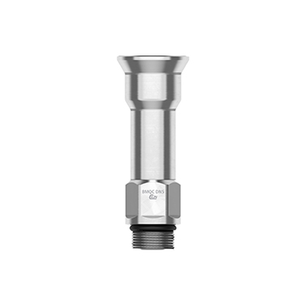
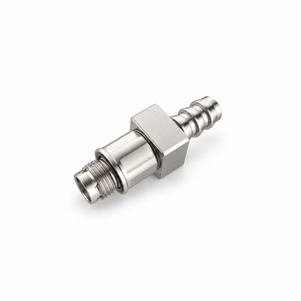
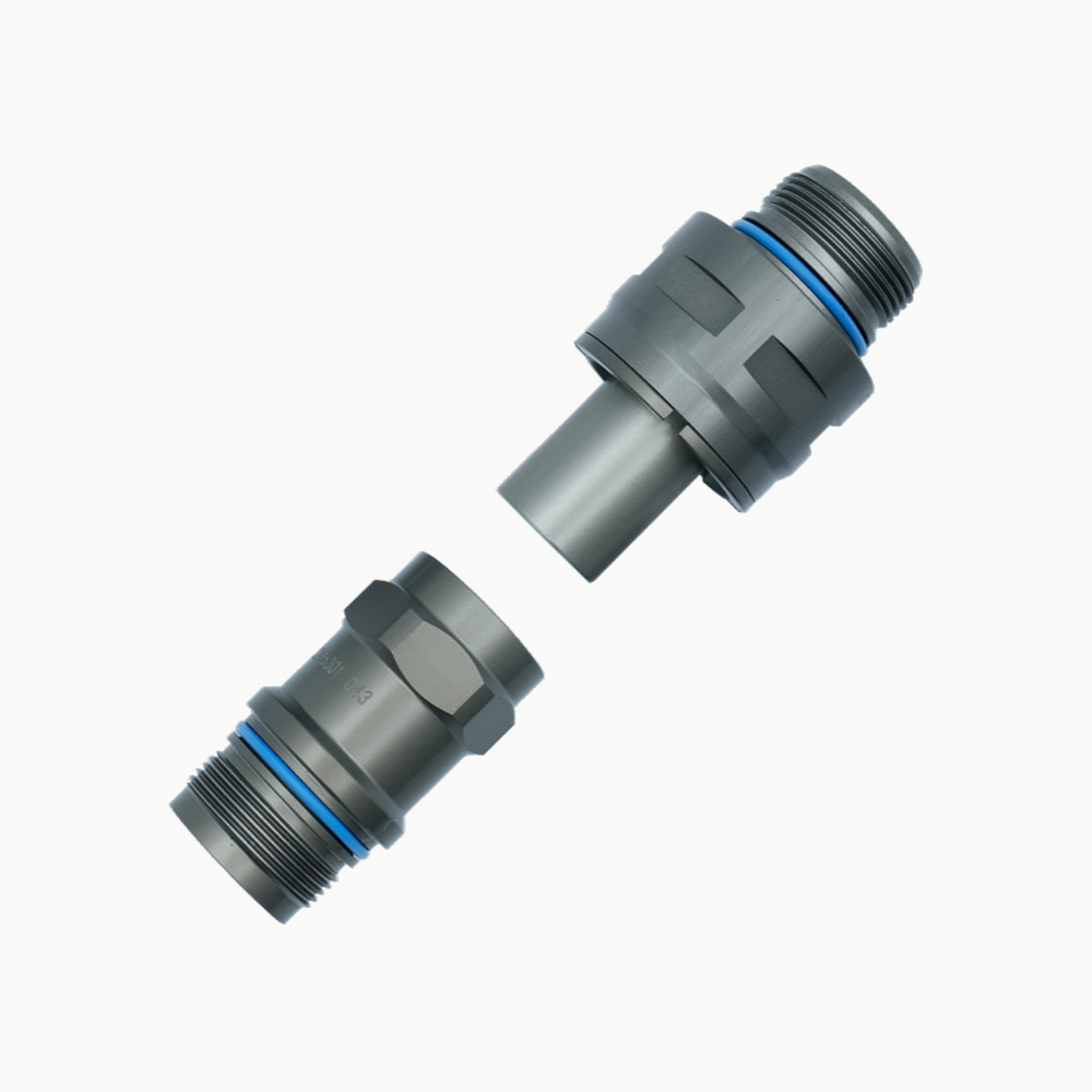
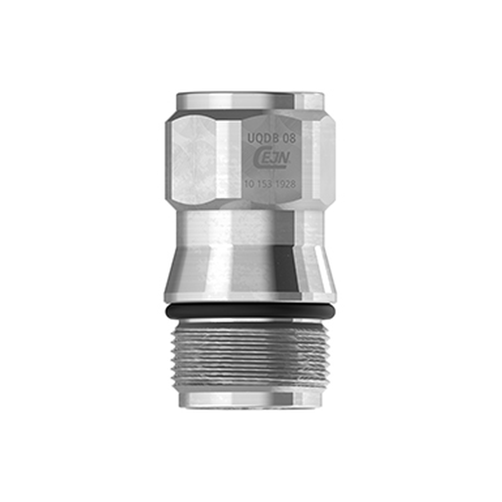
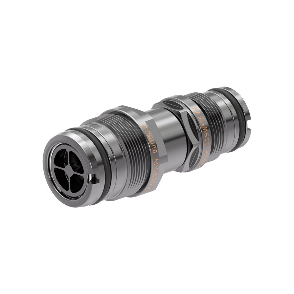
This blind-mate coupler is a guided, fixed-mount alternative to a floating connection. The image shows a CYSBI08 reference unit, while the documented range covers several nominal diameters with distinct dimensions.
Construction and interfaces
The manufacturer describes an aluminum-alloy body and no integral locking feature. Equipment-level guides, stops and retainers must establish the load path and prevent unintended withdrawal after the halves engage.
Selection
Review mating alignment against both drawings and actual panel tolerances. The supplier's stated misalignment value is a series statement and must be verified for the selected size, mounting and installed conditions.
Configuration options
Choose an exact diameter and corresponding socket/plug combination, end terminations, seals, material finish and mounting geometry. The reference photograph establishes the series style, not a universal configuration sheet.
Application limits
Do not substitute the fixed and floating styles solely because both are blind-mate. External retention, insertion travel, pressure duty, coolant compatibility and replacement access all remain controlled project inputs.