Technical selection
Specifications and configuration
Reference — CYFBI
| Parameter | Documented value / configuration |
|---|---|
| Effective diameter options | DN3 to DN12Conditions: scope: series range; select exact order code |
| Body material | Aluminum alloyConditions: scope: body statement; wetted material and coating need exact drawing |
| Maximum misalignment compensation | ±1.0 mmConditions: scope: manufacturer series claim; installed mounting and exact configuration must be verified |
| Retention | No integral locking; requires external structure for lockingConditions: scope: series description |
| Listed working pressure | 20 bar listed for the CYFBI series barConditions: scope: Manufacturer series summary; not a paired pressure-temperature-coolant approval or exact order-code rating |
| Listed operating temperature | -40 to +125 degCConditions: scope: Manufacturer series summary; seal, coolant and pressure-temperature pairing require exact configuration review |
Manufacturer series reference. Confirm the exact order code, mating parts and stated conditions for the quoted configuration.
Overview
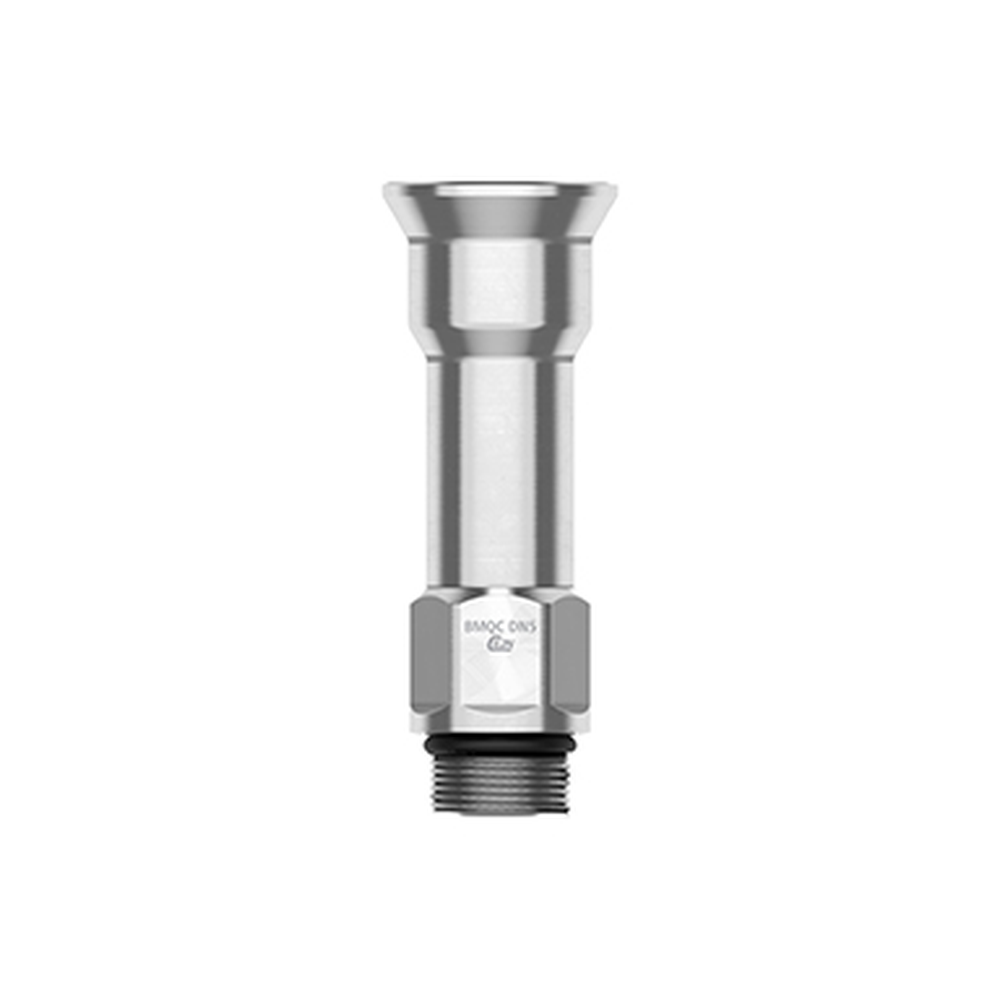
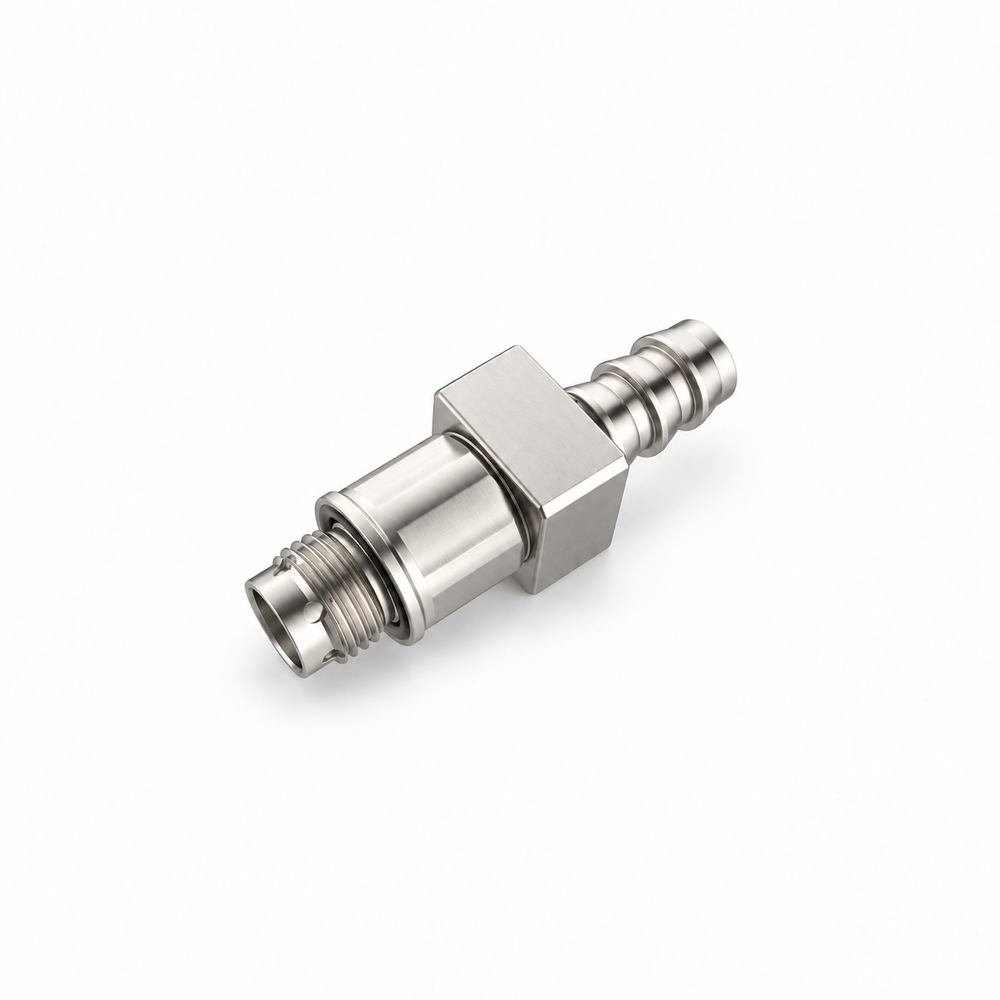
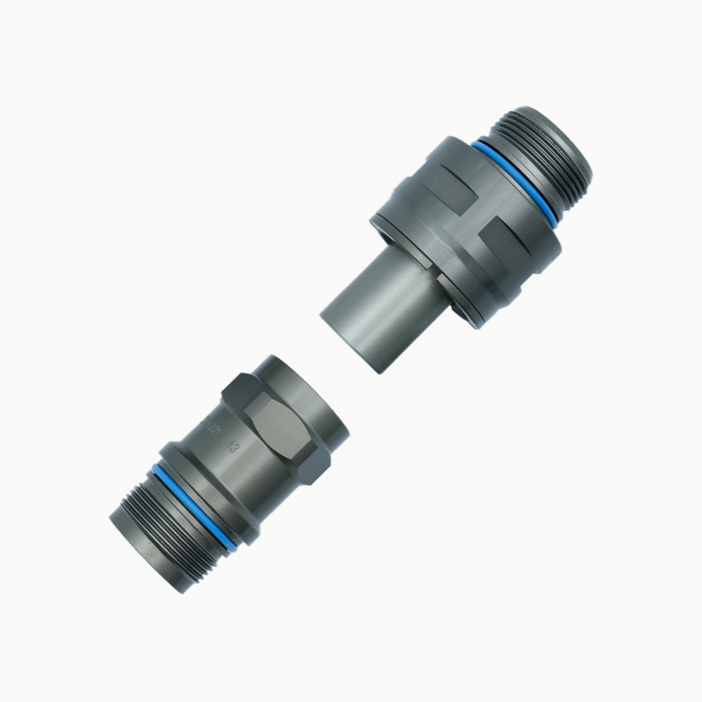
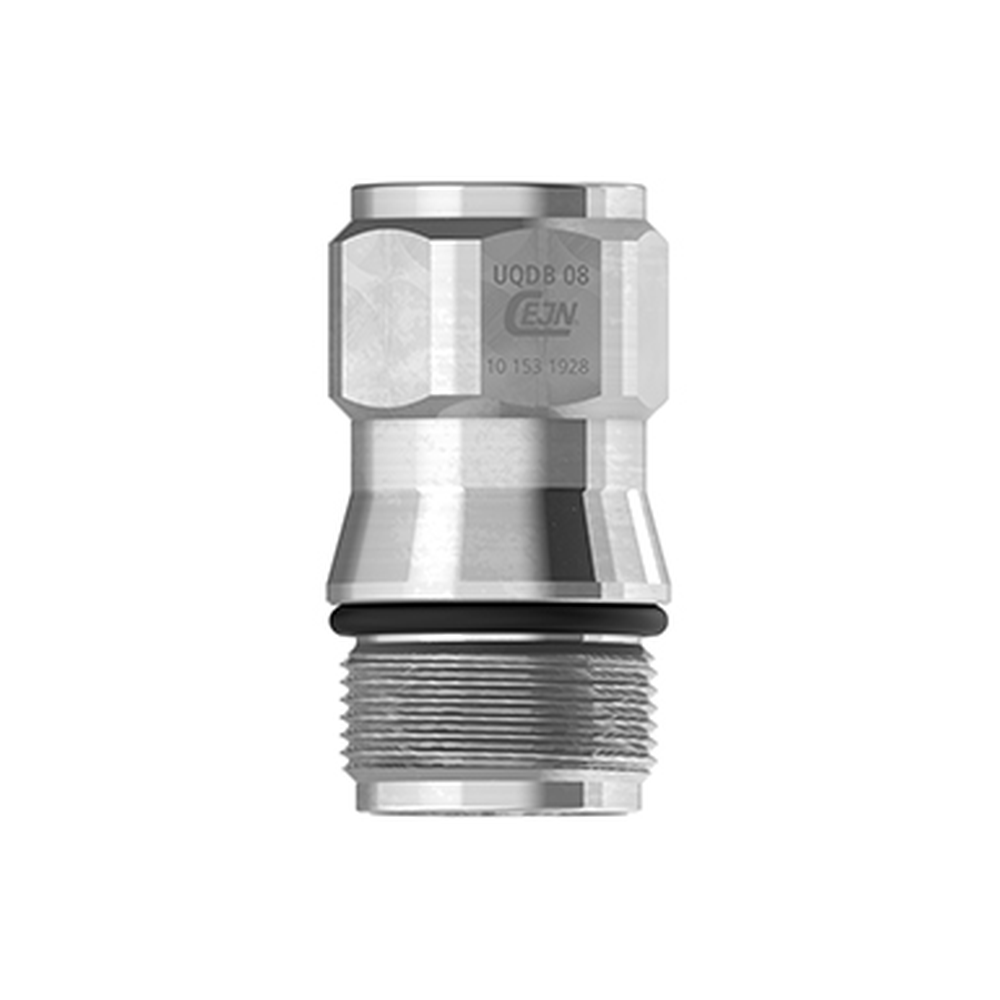
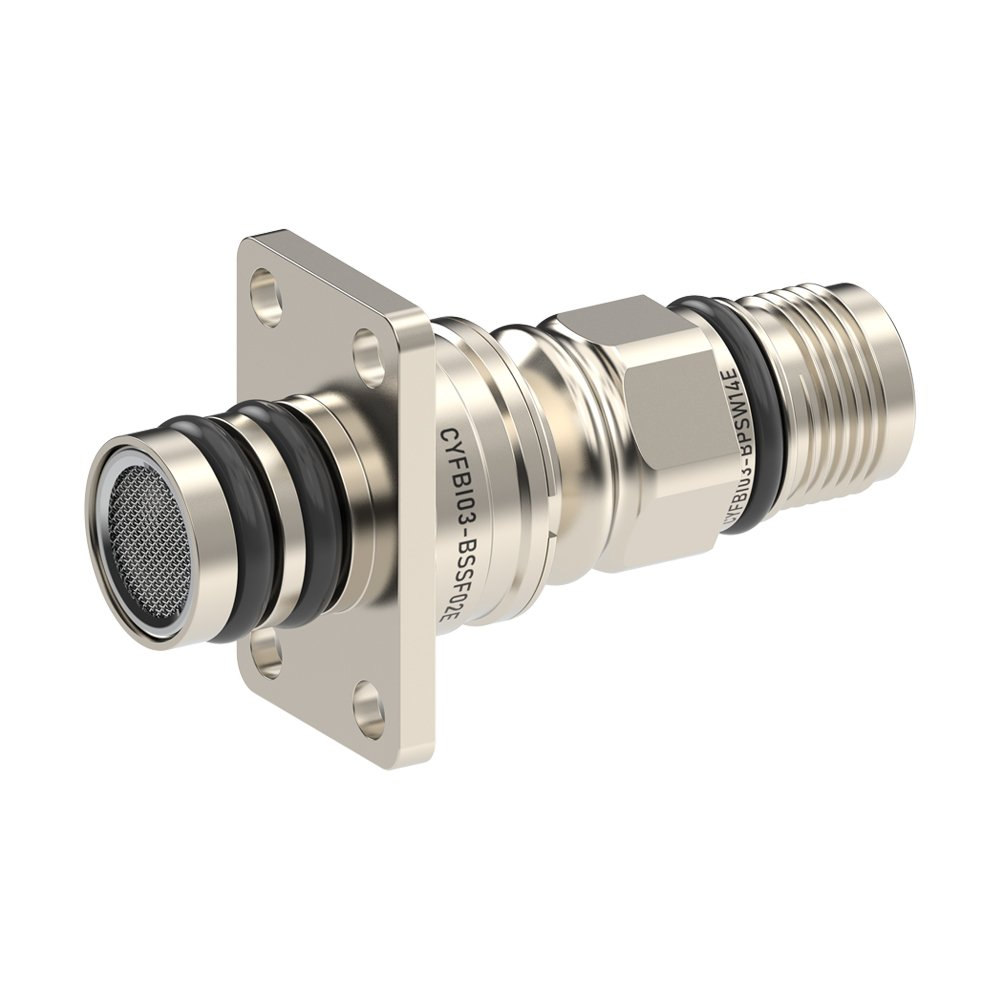
A floating blind-mate connection permits guided engagement where the equipment architecture provides insertion motion and a suitable retention structure. The pictured CYFBI03 example represents this series construction, not the dimensions of every offered diameter.
Construction and interfaces
The supplier describes an aluminum-alloy body and a floating engagement arrangement without an integral lock. The rack or module structure therefore has to control guidance, retention and service movement outside the coupling itself.
Selection
The series lists DN3 through DN12 variants and a maximum misalignment compensation claim. Treat that claim as supplier-series guidance only; validate the actual datum stack, insertion path, paired components and mounting tolerance for the selected size.
Configuration options
Select the nominal diameter, mating half, mounting features, end termination, seal and coolant-exposed materials for the actual order configuration. Body material alone is not a complete wetted-material declaration.
Application limits
The depicted example may not represent every size or end connection. No universal alignment, pressure, leakage or cross-brand compatibility promise is inferred from the reference image or series summary.